For the auxiliary and protection system for the plant, they need supplies to be in 6.6kV/AC, 415V/AC, 220V/DC, 24V/DC and 220V/AC. All this supply will come from the generation of the plant it’s own. Therefore it needs the switchgear system to arrange and distribute all the supply to the devices accordingly.
This switchgear system also connected to the black start diesel and emergency diesel generators. These two generators are used when there are emergencies like system trip or suddenly lost of supply. During these situations, the emergency generator will automatically cut in and supply 415V to the 415V feeder bus, and the operator will need to manually switch on the black start diesel generator manually to supply 6.6kV to the feeder.
Sunday, June 6, 2010
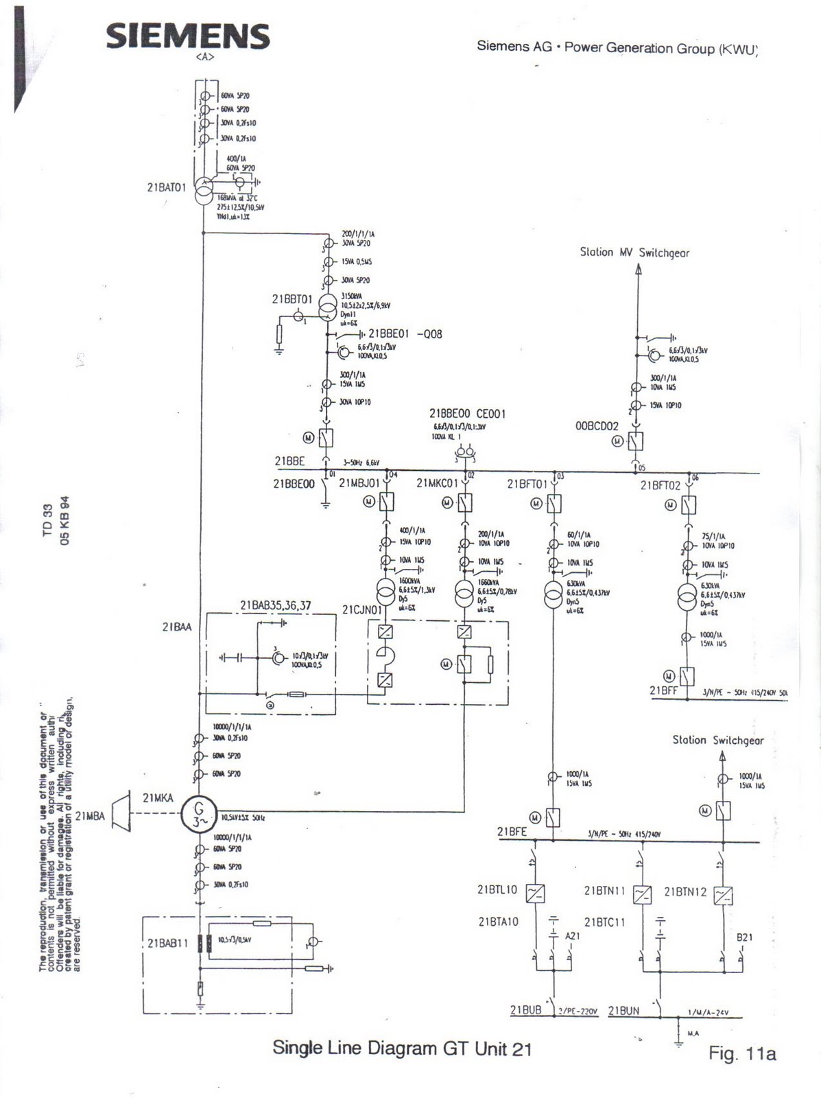
GT and ST single line diagram
Before going into detail of electrical knowledge, the basic flow of this plant is necessary for us to study. The first drawing that we are exposed to is the single line diagram of Gas turbine generator and steam turbine generator.


For both gas turbine and steam turbine generator single line diagram, they are having the same concept of electrical flow. First the generated power is 10.5kV which will be stepped up to 275kV then send to national grid. At the same time, the generated voltage will then stepped down for the excitation system and the gas turbine control supply.

Later this single line diagram will be further connected to the switchgear drawing and switchyard connection.
Electrical Department
Entering the seventh week of training (16 MAY 2010), I am now in the electrical department. Being the first day in this department, everything seems to be nice. The manager and engineer are friendly and willing to share knowledge to us. Since I am an electrical power student, I can’t wait to learn the practical things about my course.
.JPG)
.JPG)
Firstly we are asked to follow the workers to the workshop, and luckily during the first day we already had the opportunity to follow the workers for a switchgear and motor maintenance. This maintenance is taken to make check the motor supply balancing, the insulation of the connection and also the physical neatness of the motor and switchgear.
.JPG)
.JPG)
Firstly we are asked to follow the workers to the workshop, and luckily during the first day we already had the opportunity to follow the workers for a switchgear and motor maintenance. This maintenance is taken to make check the motor supply balancing, the insulation of the connection and also the physical neatness of the motor and switchgear.
Saturday, May 22, 2010
Measurement and analysis
Since I enter the Control and Instrumental department, I had a lot of opportunity to learn about measurement instrument. All these instruments are used to measure temperature, pressure, mass flow rate, volume flow rate, level, filter clog and so on.
First I want to introduce about RTD, resistance temperature detector. It is used to measure temperature with the concept “relationship between resistance and temperature”. Both of these parameters are in proportional, which means, the higher the temperature, the higher the resistance.
Another temperature measurement instrument is thermocouple. It used the seebeck effect to build this instrument where it uses two different metals which bonded together. When the hot junction of the metal is being exposed to certain temperature, voltage will be produced.

On the other hand, other than measuring temperature, we need to measure pressure too. Instrument normally used is differential pressure transmitter. Other then measuring pressure, this instrument can be used to measure level and filter clog too.
Other then all that I mention before this, there are still many transducer that I learned. It’s been a great experience to be in this control and instrumental department, however, my training had almost come to the sixth week. Next week I am going to transfer to electrical department. At here, I wish to thanks to all staffs in this department that had taught me a lot during these six weeks, especially, our “Tok Guru”, Mr. Tawang.
First I want to introduce about RTD, resistance temperature detector. It is used to measure temperature with the concept “relationship between resistance and temperature”. Both of these parameters are in proportional, which means, the higher the temperature, the higher the resistance.
Another temperature measurement instrument is thermocouple. It used the seebeck effect to build this instrument where it uses two different metals which bonded together. When the hot junction of the metal is being exposed to certain temperature, voltage will be produced.
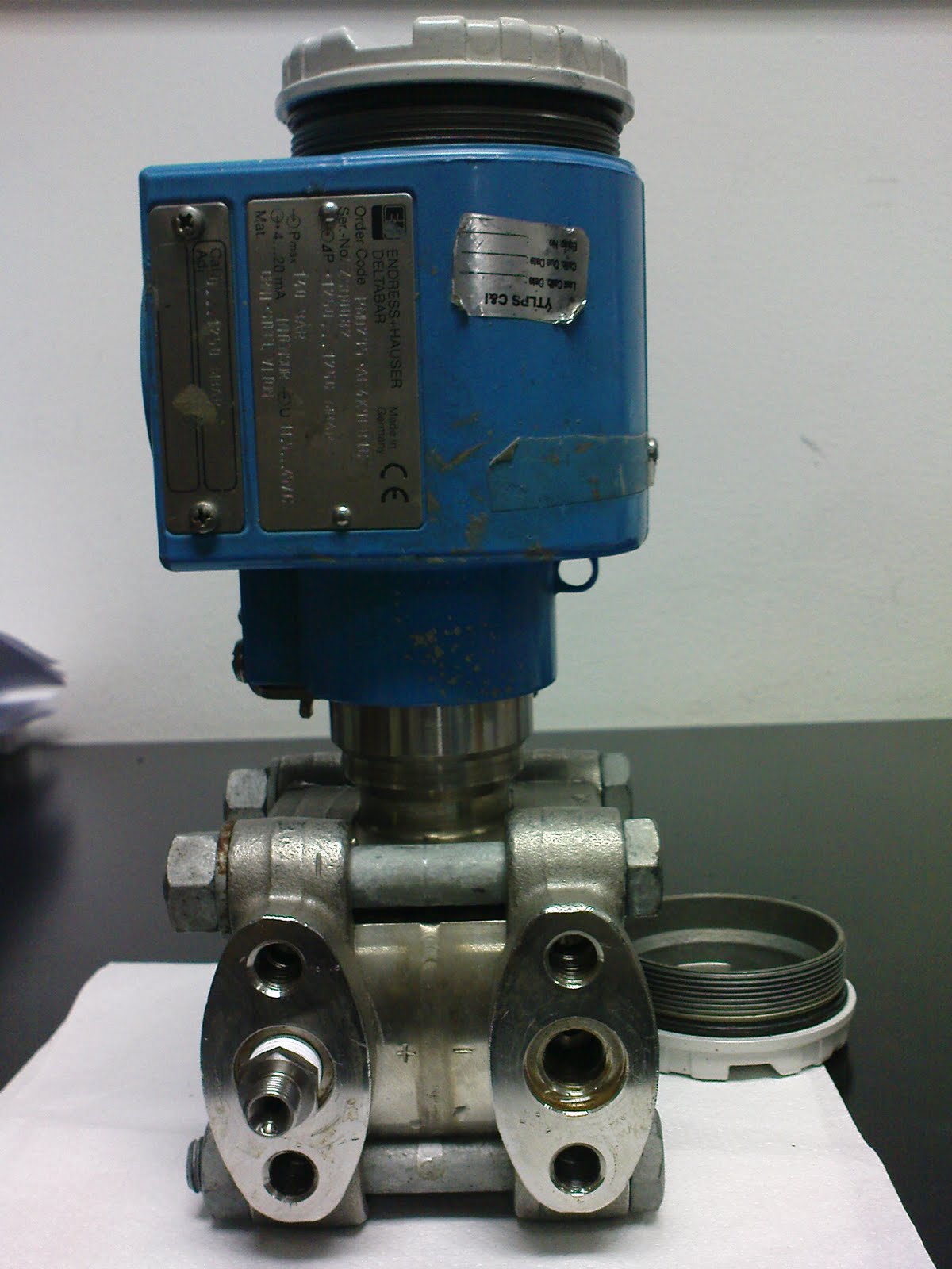
On the other hand, other than measuring temperature, we need to measure pressure too. Instrument normally used is differential pressure transmitter. Other then measuring pressure, this instrument can be used to measure level and filter clog too.
Other then all that I mention before this, there are still many transducer that I learned. It’s been a great experience to be in this control and instrumental department, however, my training had almost come to the sixth week. Next week I am going to transfer to electrical department. At here, I wish to thanks to all staffs in this department that had taught me a lot during these six weeks, especially, our “Tok Guru”, Mr. Tawang.
Combustion chamber ball valve operation sequence
Today I learn about ball valve operation sequence which located at the combustion chamber. These ball valves control the amount and the flow of the fuel gas flow into the burner inside the combustion chamber. There are three different modes in the burner. They are diffusion, premix and pilot valve.
For diffusion mode, the fire flame is yellow colour, produce No and Co, burn stable and not complete burning. Premix mode, the fire flame is blue colour, produce less pollution, burn unstable and complete burning. Beside that, pilot node is used to help premix mode to burn in a higher stability.
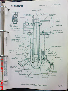
Because of all these characteristic, diffusion mode is used during start up and shut down of the combustion chamber, while premix and pilot mode are used during normal operation of the combustion chamber.
Friday, May 14, 2010
Hardware and Software
After several days training in C&I department, I observe that every time when the engineer going to work, they will bring some kind of drawing which I don’t really understand. Fortunately, Mr. Tawang gave us some introduction about it today. During the design of this plant’s control and instrumental system, they need to have the hardware and software drawing since this system is very complicated. For hardware drawing it explain about the type of transducer, the connection from field to control room, the location and so on. Workers need it to understand the construction of the instrument that they are going to deal with.
On the other hand, software drawing is the digital logic which connected to a particular transducer. These drawing explain the open loop control, close loop control and protection of the instrument.
All this drawings are kept in tick files in the library which I found very interesting. I wish I could explore more about it in the future.
C&I Structure
.JPG)
So far, I had gone to control room and PCC. These places had a lot of cabinet which control the plant. Today, I had the chance to learn about details of the control and instrumental structure.
The operation condition of the plant is important for the operator to monitor it from time to time, therefore, transducers or sensors like magnetic flowmeter, DP transmitter, RTD, thermocouple, and so on, are connected to every machines in the plant. All these transducers then will convert the paramenters like temperature, pressure, flow rate and so on, into electrical form, then sent it to a card in a cabinet which called the ET 200. Later it will send to PCC automation cabinet, then the data will pass into fiber optic cable and transmit to control room’s busses cabinet. After passing through several server, data will then send to computer to display. This is the general idea of how the data is being processed.
After knowing all this, I realize that, to design a control and instrumental structure is very complicated and it involve a lot of knowledge like mechanical, micro p, digital logic, and so on. This is a good experience for me to know the application of my knowledge learn during university.
Subscribe to:
Posts (Atom)